Fitting It All Together
Practical Circuits
|
To Engage Multimedia Mode Press Play |
In amateur radio circuits it is very common to diagram them using a block diagram. In this type of diagram each major part of the circuit is represented as a box. The diagram then shows how all of the boxes connect to each other.

A transmitter is a device that produces a radio-frequency (RF) signal. Powerful transmitters are needed to put television and radio broadcast stations' signals into the air. Amateur radio operators, however, use low powered transmitters to send their signals to each other. A transmitter simply produces an electrical signal that can be sent to a distant receiver.
The signal emitted from a transmitter is called the radio frequency carrier, or RF carrier. When transmitting Morse code you simply use a telegraph key to switch the carrier on and off in the proper code pattern. When transmitting voice signals, however, extra circuitry is needed in the transmitter to add the voice content to the carrier. This extra circuitry is called a modulator.
Although amateur transmitters range from very simple to elaborate, they generally have two basic stages, an oscillator and a power amplifier (PA).
The transceiver has replaced the need for separate receivers and transmitters in most amateur stations. The transceiver combines the circuitry needed for receiving and transmitting in one package. Some of these circuit sections may perform functions for both transmitting and receiving, while other sections are dedicated solely to transmitting or receiving functions. To simplify explanation we will discuss transmitter and receiver circuits individually since the principles of operation in a transceiver are the same.

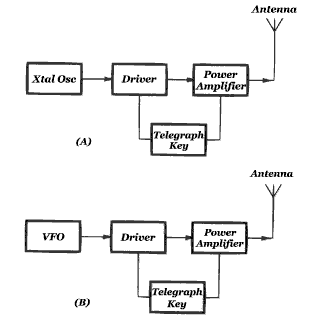
Diagram A shows a block diagram of a simple amateur transmitter. This transmitter produces CW (continuous-wave) radio signals when its key is closed. This crystal-controlled transmitter consists of a crystal oscillator followed by a driver stage and a power amplifier. This type of transmitter uses a quartz crystal to keep the frequency of the radio signal constant.
To add information to the transmission we must modulate the radio signal. This means we are changing the radio signal by adding information to it. By simply pressing the key of a CW transmitter and holding it down you create a radio-frequency carrier (RF carrier), which is also known as an unmodulated carrier. A radio-frequency signal that has a constant amplitude and is unmodulated is called a RF carrier. When you use the key to turn the signal on and off to produce Morse code dots and dashes, however, you modulate the signal. Modulation is simply the process of varying an RF carrier in some way to send information.
Crystal oscillators are not always practical because a different crystal is needed for each operating frequency. This tends to become quite expensive as well as impractical. By using a variable-frequency oscillator (VFO) in place of the crystal oscillator, as shown in diagram B above, we can change the transmitter frequency whenever we want. The transmitter operating frequency can be controlled by either a crystal oscillator or a variable-frequency oscillator, whichever is practical.
A telegraph key may connect to one or more of the transmitter sections. In the diagram above we show the key connected to both the driver and power amplifier stages. Normally you would not key the oscillator stage, as this may cause the oscillator to change frequency slightly.
Of course all transmitters also require a source of operating voltage, but we have left the power supply off the diagrams for simplicity.
As we mentioned before, when a radio signal or carrier is modulated its characteristics are changed in some way in order to convey information, thus information is transmitted by modulating any property of a carrier. For example the frequency or phase of a carrier can be modulated. Frequency modulation (FM) and phase modulation are very closely related. The phase of a signal is not able to be varied without also varying the frequency and vice versa. UHF and VHF communication make use of phase modulation (PM) and frequency modulation (FM). They also feature good audio fidelity and a high signal-to-noise ratio.
The carrier frequency is varied or modulated by changes in voltage that represent information to be transmitted. A microphone, computer modem, or even a video camera may be the source of this information. The carrier frequency changes in proportion to the rise and fall of the modulating voltage.
Because the transmitter is a sending device it sends a RF signal to the transmitting antenna from which the signal is radiated into the air. At some point that same signal produces a voltage in a receiving antenna. That AC voltage then goes from the receiving antenna into a receiver. The receiver converts the RF energy into a audio-frequency (AF) signal. This AF signal can be heard in headphones or from a speaker.
Receivers take electronic signals out of the air and convert them into what we can see or hear. The receiver is a very important part of an Amateur Radio station.
The main function of any radio receiver is to change RF signals to signals that we can hear or see. A good receiver can even detect weak radio signals and separate them from other signals and interference. A good receiver will also stay tuned to one frequency without drifting. A receiver's ability to detect weak signals is called sensitivity. Its ability to separate a desired signal from undesired signals is called selectivity. Stability is a measure of a receiver's ability to stay tuned to a particular frequency. A good receiver will be very sensitive, selective, and stable, and can be very simple or complex.
The heart of a receiver is the detector. It is where the information is collected from the signal. "Crystal sets" using galena crystals and "cat's whiskers" were an early form of amplitude modulation (AM) detector. AM is generated by varying the amplitude of an RF signal in response to an information source, such as a microphone. The "cat's whisker" is just a thin piece of stiff wire, but with the galena crystal it forms a point-contact diode.
More sensitive and selective receivers are needed today, because crystal sets cannot receive signal sideband (SSB) and CW signals properly, but it does show you how simple a receiver can be. A more practical receiver needs some way to tune different frequencies. A receiver that has a tuned circuit at the input to select signals on different frequencies is known as a tuned-radio-frequency (TRF) receiver.
The next step up in receiver complexity is shown in the diagram below.

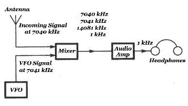
This type of receiver uses direct-conversion, meaning the RF signal is converted directly to audio in one step. The incoming signal is mixed with a signal from a VFO in the mixer stage. In our diagram we mix an incoming signal at 7040 kHz with a signal from the VFO at 7041 kHz. The output of the mixer contains signals at 7040 kHz, 7041 kHz, 14081 kHz, and 1 kHz. (These are the original signals and their sum and difference frequencies.) One of these signals (1 kHz) is within the range of human hearing. We can use an audio amplifier and hear it in the headphones.
By simply changing the VFO frequency other signals in the range of the receiver can be converted to audio signals. Direct conversion receivers are capable of providing good reception with simple and inexpensive circuits.

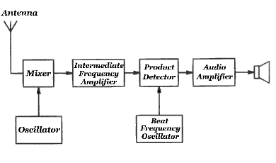
A simple superheterodyne receiver for CW and SSB is diagramed above. In this type of receiver the mixer produces a signal at the intermediate frequency (IF). The amplifier after the mixer is designed to be most efficient at the IF. This receiver solves the selectivity/bandwidth problems by converting all the signals to the same IF before finally filtering and amplifying them. A second mixer called a product detector is used to receive SSB and CW signals. The product detector mixes the IF signal with a signal from the beat-frequency oscillator (BFO). The BFO then converts the received signal information from the IF to the audio range. The product detector output also contains audio that can be amplified and then sent to a speaker. Almost all modern manufactured receivers have two or three IF stages, with the first IF around 73 MHz, the second often around 9 MHz, and the third usually around 55 kHz. These extra conversions help solve some problems and limitations of single conversion methods.
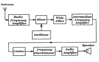
FM superheterodyne receivers are similar, but with a few different stages. They have a wider bandwidth filter and a different type of detector. One of the common FM detectors is the frequency discriminator. Its output varies in amplitude as the frequency of the incoming signal changes.
A limiter stage between the IF amplifier and the detector is also included in most FM receivers. This makes the receiver less sensitive to amplitude variations and pulse noise than AM or SSB/CW receivers. As the name implies, the limiter output remains almost constant when the signal level fluctuates. Noise pulses are also amplitude/modulated signals. The limiter does not pass them on to the detector. This feature makes FM popular for mobile and portable communications. The diagram below shows the main stages of an FM receiver.

Modern amateur radio transceivers have filters built in to attenuate (reduce) harmonic radiation so they seldom create harmonic related interference. Harmonic interference must be cured at your transmitter. It is your responsibility as a licensed amateur, and you must see that harmonics from your transmitter are not strong enough to interfere with other services.
There are several possible cures for harmonic interference. If you try each step in the order that we introduce them, chances are good that your problem will be quickly solved. You should be familiar with these three filters: the low-pass filter, the high-pass filter, and the band-pass filter. Filters allow certain frequencies through the circuit while blocking others. They allow various kinds of equipment to operate on different frequencies without interfering with each other, but under certain conditions some equipment may need a little extra help. Having a basic understanding of filters and their applications will allow you to solve interference problems.
Low-Pass Filters
A low-pass filter passes all frequencies below a certain frequency, called the cutoff frequency. The filter's cutoff frequency is measured by putting a variable frequency signal into the filter. The input signal power is kept constant while increasing the frequency. At the same time we measure the filter output power, which at a certain frequency will begin to decrease. When the output power has decreased to half the input power we have found the cutoff frequency. All frequencies above the cutoff frequency are attenuated or significantly reduced in amplitude. The cutoff frequency depends on the design of the low-pass filter.
The low-pass filter is always connected between the transmitter and the antenna, as close to the transmitter as possible. The filter needs to have the same impedance as the feed line connecting the transmitter to the antenna. Filters should only be used in a feed line with a low SWR. The cutoff frequency has to be higher than the highest frequency used for transmitting. Most modern transmitters contain a low-pass filter in their output circuitry to prevent excess harmonic radiation.
High-Pass Filters
A high-pass filter allows all frequencies above the cutoff frequency to pass through and attenuates those below it. A high-pass filter should be connected to a television set, stereo, or other home-entertainment device that is being interfered with. This filter will attenuate the signal from an amateur station. At the same time it allows higher frequency television or FM-broadcast signals to pass through to the receiver. This reduces the amount of lower frequency signals that might overload a television set and cause interference.
A high-pass filter should be connected as close to the device as possible. You may want to put it inside the device if you do not mind opening its casing. You can also attach it directly to the antenna terminals on the back of the device. If the device belongs to your neighbors, have them contact a qualified service technician to install the filter. That way you are not held responsible if something goes wrong with the device later.
Band-Pass Filters
A band-pass filter houses a combination of a high-pass filter and a low-pass filter. It passes a desired range of frequencies and rejects signals above and below the two cutoff frequencies. These filters are commonly used in the IF stage of a receiver to provide different degrees of rejection. You would use a very narrow filter for CW reception, and a wider filter for SSB and AM double-sideband reception. The filter allows the receiver IF stages to select signals within a certain frequency range and block those outside that range.
Antenna Switch
An antenna switch connects one transmitter, receiver, or transceiver to several antennas. You can switch to one antenna to another by using a simple switch. The antenna switch is connected at the point where the feed lines from all the antennas come into the station. Even if you only have one antenna, you may find an antenna switch useful, as many amateurs use one to switch between their antenna and a dummy antenna, or dummy load.
SWR Meter
The SWR meter measures standing-wave ratio. Standing-wave ratio is a good indicator of how well your antenna system is working. If you install a SWR meter in your station you can keep an eye out for problems with your antenna. By spotting the problems early you can fix them before they damage your equipment. SWR meters can be connected at several points in your station. One good place to connect the meter is between the antenna switch and the transceiver. Most amateurs connect their SWR meter as close to the transmitter output as possible.
Antenna Tuners
An antenna tuner lets you use one antenna on several bands, and may also allow you to use your antenna on a band it is not designed for. The antenna tuner matches (tunes) the impedance of the load (the antenna and feed line) to the impedance of your transmitter. The antenna tuner is usually connected right where the antenna comes into the station. If you decide to use an antenna tuner you will need a SWR meter. It must be connected between the antenna tuner and the transmitter or transceiver.
Telegraph Key
Since Morse code is transmitted by switching the output of a transmitter on and off, inventive radio operators have developed several devices to make this switching easier. The simplest kind of code-sending device is one you are probably already familiar with: the telegraph key. A telegraph key is just a simple switch. When you press down on the key, the contacts meet and the transmitter produces a signal.
Microphones
A microphone converts sound waves into electrical signals that can be used by a transmitter. All voice transmitters require a microphone of some kind. Like a code key, the microphone connects directly to the transmitter.
Duplexer
You can think of a duplexer as a frequency-sensitive signal steering device. If you have a VHF/UHF radio with two antenna connectors, for example, and you want to connect them both to a single dual-band antenna, the duplexer will insure that the signals coming out of the VHF side will go to the antenna but not be fed back through the UHF side, and that the signals coming out of the UHF side will not be fed into the VHF side, but instead will go to the antenna.
"Ham-Shack.com", Copyright 1997-2009 Jonathan and Sara Imberi All rights reserved.